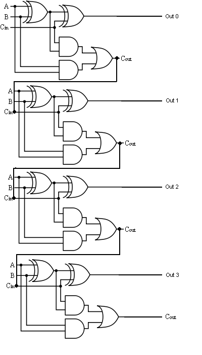
4-bit Full Adder Circuit Diagram
Boolean algebra Adder circuit logic using digital boolean implementation function diagram implement Adder half xor logic ripple rangkaian adders transistor kombinasi
11+ 4 Bit Adder Circuit Diagram | Robhosking Diagram
Adder bit parallel four circuit diagram binary subtractor logic digital block example geeksforgeeks detailed discussion 😊 four bit parallel adder. 4 bit binary adder circuit / block diagram 4 bit binary incrementer
Adder circuit diagram schematic bit works figure
The answer is 42!!: four bit full adder tutorialDigital logic design: full adder circuit Full adder circuit diagramCs 3410 spring 2018 lab 1.
11+ 4 bit adder circuit diagramAdder alu nor nand Full-adder circuit, the schematic diagram and how it works – deeptronicAdder bit circuit half make logic diagram comparator gates first electronics questions cout second there only puzzle connecting solved which.

Adder bit logisim using circuit alu cs complement create unsigned lab1 lab cornell courses labs edu save re ta sub
Adder bit four logic gates byte 4bit nand boolean not nor values possible possibilities hold answer trick function known createAdder bit implementation gates nand diagram only add Logic gatesDownload 4 bit adder circuit stick and logic diagram.
Binary circuit output geeksforgeeks incremented .


boolean algebra - 2 bit adder implementation - Mathematics Stack Exchange

CS 3410 Spring 2018 Lab 1

Digital Logic Design: Full Adder Circuit

Full Adder Circuit Diagram

Full-Adder Circuit, The Schematic Diagram and How It Works – Deeptronic

logic gates - How to make 2 bit or more half adder circuit - Electrical
The Answer is 42!!: Four Bit Full Adder Tutorial

4 Bit Binary Incrementer - GeeksforGeeks

11+ 4 Bit Adder Circuit Diagram | Robhosking Diagram